Building an In-House Dev Environment on Kubernetes Part 3: Kubernetes Device Plugin for LPU
Hello! I’m Younghoon Jun, a DevOps Engineer on the ML team at HyperAccel.
This post is the third installment of the Building an In-House Dev Environment on Kubernetes series!
In Part 1, we covered the background, overall design, and direction of building a Kubernetes-based development environment. Part 2 introduced the strategy and process for building an ARC-based CI/CD infrastructure to overcome the structural limitations of self-hosted runners. In this third article, we will discuss the Device Plugin required for utilizing custom resources on Kubernetes.
HyperAccel is a company that builds LPU(LLM Processing Unit) devices specialized for LLM inference. To make Kubernetes recognize the LPU as a custom resource and enable smooth scheduling, a Device Plugin developed specifically for the LPU is required.
In this article, we will explore the following topics under the theme of LPU Device Plugin:
First, we explain the operating principles and detailed mechanics of the Kubernetes Device Plugin. Then, we introduce the development process of the device plugin for HyperAccel’s first-generation FPGA-based LPU and how it is provided. Next, we briefly introduce the development process of the device plugin for Bertha , our upcoming ASIC-based LPU. Finally, we introduce DRA (Dynamic Resource Allocation), a technology gaining significant attention, and explain how DRA relates to the scheduler and Device Plugin in Kubernetes.
Kubernetes Device Plugin
The Kubernetes Device Plugin framework is a standard interface that allows custom devices such as GPUs, FPGAs, and NICs to be exposed and managed within a Kubernetes cluster.
By default, Kubernetes can only recognize CPU and memory resources. Without a Device Plugin, Kubernetes has no information about custom devices, making it difficult to distinguish between hardware, check device status, or use them as criteria for Pod scheduling. Device Plugins enable vendors to support their hardware without directly modifying Kubernetes source code.
Why Do We Need a Device Plugin?
This approach was difficult to maintain because it required understanding the vast Kubernetes codebase. It also lacked scalability, since the code had to be modified every time new hardware was introduced.
In summary:
Improved maintainability and scalability: Kubernetes focuses solely on container orchestration, while hardware control logic is handled by Device Plugins built by manufacturers (NVIDIA, AMD, HyperAccel, etc.).
Support for diverse hardware: Not just GPUs, but also high-performance networks (SR-IOV), cryptographic accelerators (QAT), and other resources can all be managed in a unified manner.
How Device Plugins Work & Workflow
Device Plugins typically run as DaemonSets and communicate with Kubelet through gRPC services on each node. The process of making devices recognizable through communication between Kubelet and the Device Plugin is as follows:
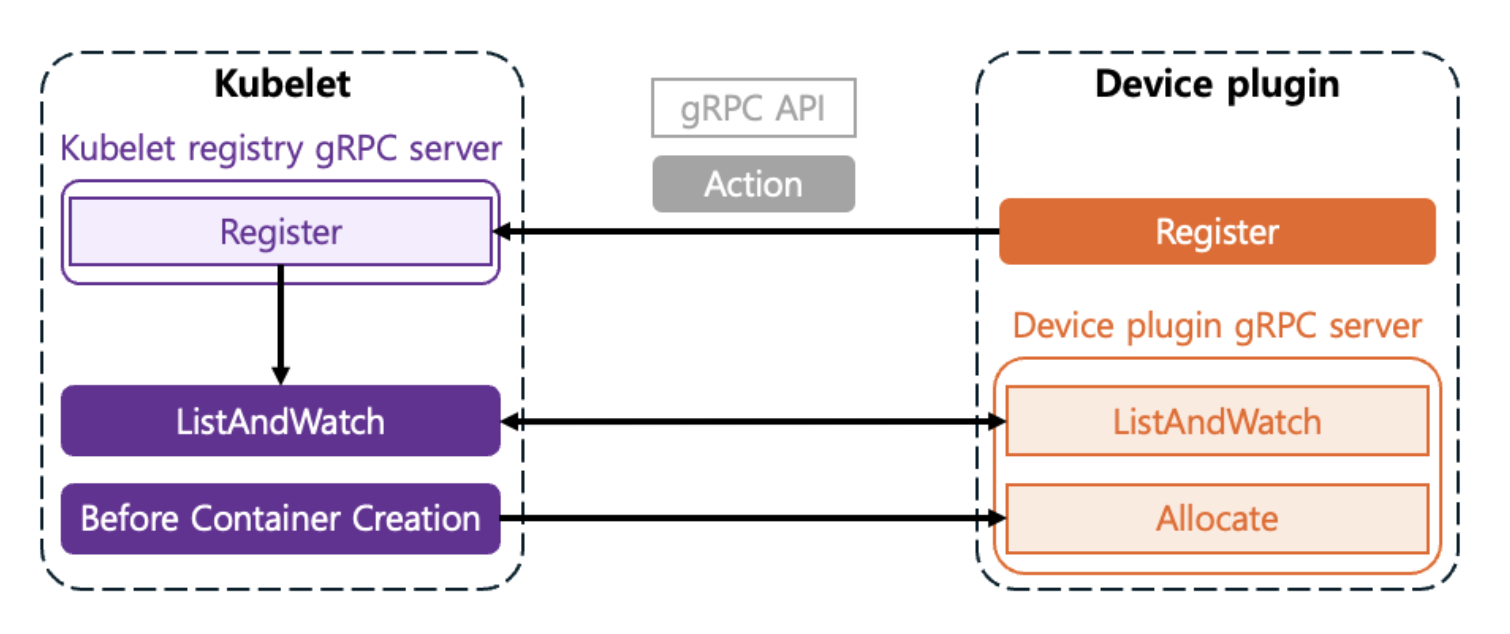
Registration
When the Plugin starts, it registers itself with
Kubeletthrough a specific path on the node (/var/lib/kubelet/device-plugins/kubelet.sock).This is the process of telling
Kubelet: “I am a plugin that manages a resource calledhyperaccel.ai/lpu!”
ListAndWatch
Kubeletperiodically requests the list of available devices from the plugin.The Plugin monitors and reports the status of devices (
Healthy/Unhealthy) in real-time toKubeletthrough theListAndWatchmethod.
Allocate
At the node level, when a user specifies
resources.limits.hyperaccel.ai/lpu: 1in the Pod spec, the scheduler places the Pod on a node that has available resources. The scheduler is responsible for selecting the node where the Pod will be placed.Once the Pod is placed on a node through the scheduler,
Kubeletcalls the plugin’sAllocatemethod. The Plugin responds with the necessary configurations (environment variables, device node paths, volume mounts, etc.) so that the container can access the device.The Device Plugin is responsible for selecting which device to allocate within the node.
So far, we have examined the process by which the Device Plugin communicates with Kubelet to make Kubernetes recognize devices. So what interface is needed when these two components communicate? Let’s look at the gRPC interface required for the Device Plugin to communicate with Kubelet.
Key gRPC Interfaces
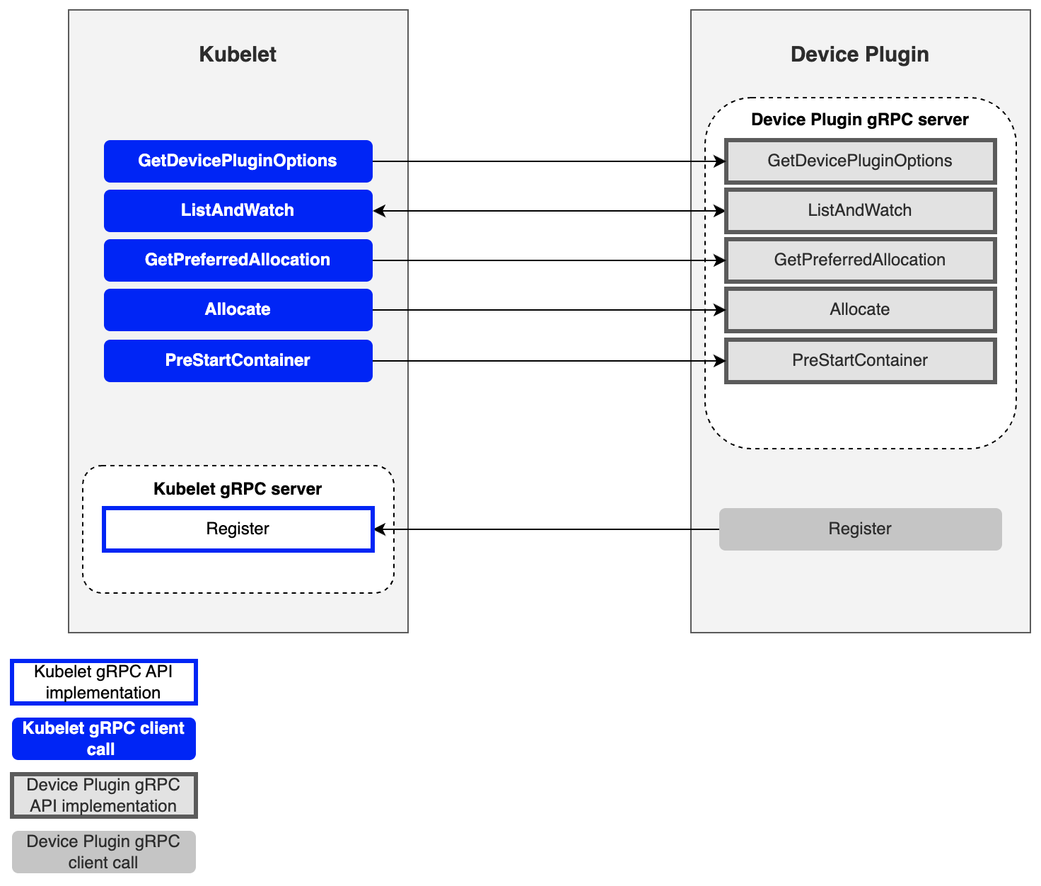
| Method | Role |
|---|---|
| GetDevicePluginOptions | Checks plugin options (periodic checkpoints, etc.) |
| ListAndWatch | Returns the device list and streams status changes |
| GetPreferredAllocation | Provides functionality to guide specific hardware selection through preference conditions |
| Allocate | Provides configuration for using specific hardware during container creation |
| PreStartContainer | Initializes the device before the container starts (optional) |
Next, we will explain how Kubernetes internal components, including the Device Plugin, allocate devices to pods during the actual device request process.
How Devices Are Allocated to Pods
We will use HyperAccel’s LPU as an example.
Detecting Available LPUs on a Node
First, let’s explain how the API Server and Kubelet detect and monitor new devices by interacting with the Device Plugin at the Kubernetes level.
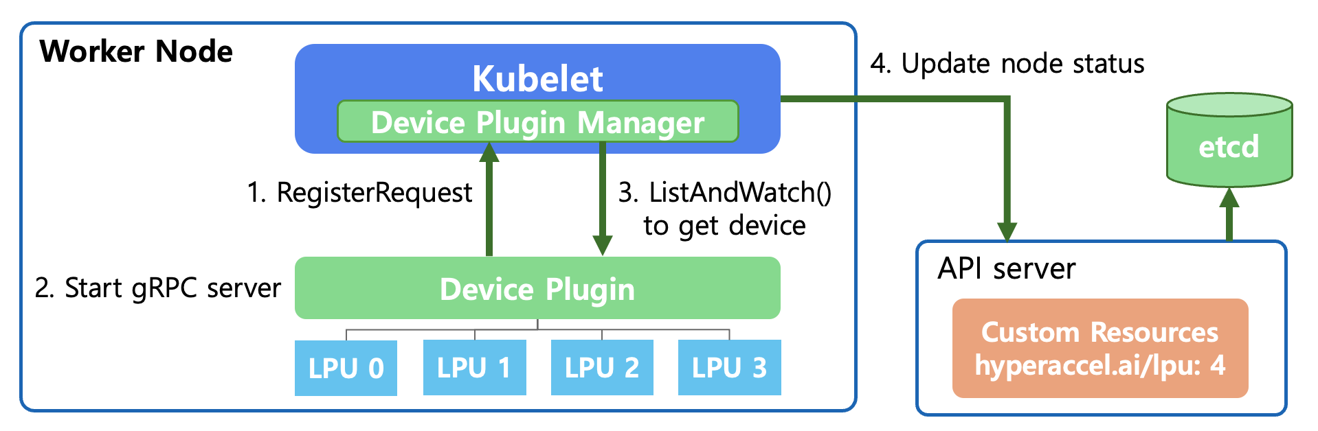
RegisterRequest (Device Registration Request)
When the Device Plugin starts, it registers the plugin with
Kubelet’s Device Plugin Manager through a Unix Domain Socket.This is the process of saying: “This node has a resource called
hyperaccel.ai/lpu, and I will manage it.”
Start gRPC Server
- The Device Plugin starts a gRPC server to communicate with
Kubelet. Through this,Kubeletcan query device status or send allocation (Allocate) requests.
- The Device Plugin starts a gRPC server to communicate with
ListAndWatch
Kubeletcalls the Device Plugin’s ListAndWatch() function.During this process, the Device Plugin detects the LPUs connected below and reports their status (Healthy/Unhealthy) to
Kubelet. This connection is maintained continuously, so it immediately notifies if any device issues occur.
Update Node Status
Kubeletsends the confirmed LPU resource information (e.g.,hyperaccel.ai/lpu: 4) to theAPI Server.The
API Serverrecords this information in etcd.Now the entire cluster knows that “4 LPUs are available on that node.”
Now, when a user creates a pod and requests the following in the YAML file, the Kubernetes Scheduler can place the pod on the appropriate node:
# User Pod YAML file

resources:
  limits:
    hyperaccel.ai/lpu: 1  # Request 1 LPU
Selecting and Allocating the Appropriate LPU for a Pod’s Request
Once the Kubernetes level is ready to use the new device called LPU through the above process, we need to look at the actual allocation process. Let’s explain step by step what happens internally in Kubernetes when a user declares “I need 1 LPU” in the YAML file.
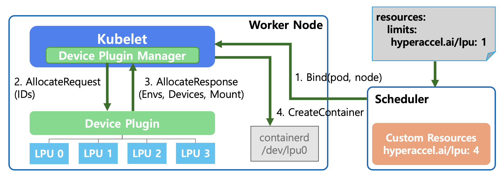
Bind(pod, node) - Pod Scheduling
The user requests
hyperaccel.ai/lpu: 1in thePodSpec.The Kubernetes Scheduler searches for nodes with IDLE LPUs across all nodes.
It selects a worker node that meets the conditions and commands (Bind): “Place this pod on the designated node!”
AllocateRequest
Kubeletconfirms that the pod assigned to it requires an LPU to run.The Device Plugin Manager inside
Kubeletrequests the Device Plugin: “I need 1 LPU, please prepare it for use.” It also passes the specific LPU ID (e.g., LPU 0) to be used.
AllocateResponse
The Device Plugin responds to
Kubeletwith the necessary configuration information to make the LPU available in the container:- Envs: Environment variables to reference inside the container
- Devices: Device paths the container needs to access (e.g.,
/dev/lpu0) - Mount: Mount paths for required libraries or driver files
CreateContainer
Kubeletrequests container creation from the container runtime (containerd) based on the received information.At this point, containerd connects the host’s
/dev/lpu0device to the inside of the container as configured, ultimately allowing the running pod to directly access the LPU hardware.
As a result, users can use the new LPU device in a safe and isolated environment simply by adding a single line — limits: hyperaccel.ai/lpu: 1 — to the YAML file, without needing to know the complex hardware setup process!
However, a question may arise from step 4 above. How does the container runtime (containerd) interpret and inject the device paths, environment variables, and mount information returned by the Device Plugin in the AllocateResponse? The standard that addresses this is CDI (Container Device Interface).
CDI (Container Device Interface): Standardizing Device Injection
The Problem Before CDI
When the Device Plugin sends the necessary configuration information to Kubelet via AllocateResponse, the container runtime ultimately interprets this to create the container. However, in this process, each vendor had its own way of injecting devices into containers.
For example, using an NVIDIA GPU in a container requires more than simply mounting the /dev/nvidia0 device file. GPU driver libraries (libcuda.so, libnvidia-ml.so, etc.), related utility binaries, and the correct paths matching their exact versions all need to be properly injected into the container. To achieve this, NVIDIA developed its own container runtime hook called nvidia-container-runtime-hook.
Other vendors’ devices — FPGAs, network accelerators (SR-IOV), cryptographic accelerators (QAT), and more — each required their own unique methods to inject device nodes, driver libraries, and configuration files into containers. This led to the following problems:
Runtime dependencies: Each vendor had to develop its own container runtime or runtime hook. NVIDIA’s
nvidia-container-runtime, AMD’sxilinx-container-runtime, and others were all needed, and they were incompatible with each other.Complex configuration management: To use both a GPU and an FPGA on a single node, multiple runtime hooks had to be combined, increasing operational complexity.
Lack of portability: Device configurations that worked with Docker sometimes didn’t work with containerd or CRI-O, because each container runtime had different device injection mechanisms.
What Is CDI?
CDI (Container Device Interface) is a container runtime-level standard specification that emerged to solve these problems. CDI declaratively defines how devices are injected into containers through a single JSON spec file. Container runtimes (containerd, CRI-O, Podman, etc.) read this spec and inject the devices into the container.
Simply put, before CDI, each vendor would say “To put my device in a container, you need to install this special runtime.” After CDI, it became “With just this JSON file, any runtime can inject my device.”
Structure of a CDI Spec File
CDI spec files are located at /etc/cdi/ or /var/run/cdi/ and have the following structure:
{
  "cdiVersion": "0.6.0",
  "kind": "hyperaccel.ai/lpu",
  "devices": [
    {
      "name": "lpu0",
      "containerEdits": {
        "deviceNodes": [
          {
            "path": "/dev/lpu0",
            "hostPath": "/dev/lpu0",
            "permissions": "rw"
          }
        ],
        "mounts": [
          {
            "hostPath": "/opt/hyperaccel/lib",
            "containerPath": "/usr/lib/hyperaccel",
            "options": ["ro", "nosuid", "nodev", "bind"]
          }
        ],
        "env": [
          "LPU_DEVICE_INDEX=0",
          "LPU_VISIBLE_DEVICES=0"
        ]
      }
    }
  ],
  "containerEdits": {
    "env": [
      "LPU_DRIVER_VERSION=1.0.0"
    ]
  }
}
The key components of the spec file are as follows:
| Field | Description |
|---|---|
| kind | A vendor domain-based name that identifies the type of device (e.g., hyperaccel.ai/lpu) |
| devices | A list of individual device definitions. Each device has a unique name |
| containerEdits | Declaratively defines changes to apply to the container |
| deviceNodes | Device file paths and permissions to expose inside the container |
| mounts | Mount configurations for driver libraries, firmware, and other required files |
| env | Environment variables to inject inside the container |
Device-level containerEdits are applied only when that specific device is requested, while top-level containerEdits are applied as common settings whenever any device of that kind is requested.
How CDI Works
The device allocation process with CDI applied is as follows:
CDI Spec Generation: The Device Plugin (or DRA Driver) detects devices on the node and generates CDI spec files for each device, storing them in the
/etc/cdi/path.CDI Device Name Passing: When allocating a device to a Pod, the Device Plugin includes the CDI device name (e.g.,
hyperaccel.ai/lpu=lpu0) in theAllocateResponseand passes it toKubelet.Container Runtime CDI Resolution: When
Kubeletrequests container creation from the container runtime (containerd), it passes the CDI device name along with the request. The container runtime finds and reads the corresponding spec file from the/etc/cdi/path, and automatically injects the device nodes, mounts, and environment variables defined incontainerEditsinto the container.Container Execution: The container runs with all device configurations applied, and the Pod can directly access the device from within.
Compared to the AllocateResponse-based flow we examined earlier, the key difference is that the complex logic for injecting devices into containers has been separated from the Device Plugin into CDI spec files. The Device Plugin no longer needs to directly include device paths, mounts, and environment variables in the AllocateResponse — it only needs to pass the CDI device name. The rest is handled by the container runtime through the CDI spec.
CDI Configuration by containerd Version
To use CDI, the container runtime must have CDI support enabled. For containerd, the level of CDI support varies by version.
| containerd Version | CDI Support Status | Configuration Required |
|---|---|---|
| Before 1.7 | CDI not supported | Not available |
| 1.7 ~ 1.x | CDI supported (default: disabled) | Manual activation required |
| 2.0 and above | CDI supported (default: enabled) | No additional configuration needed |
For containerd versions 1.7 and above but below 2.0, CDI must be explicitly enabled in /etc/containerd/config.toml.
[plugins."io.containerd.grpc.v1.cri"]
  enable_cdi = true
  cdi_spec_dirs = ["/etc/cdi", "/var/run/cdi"]
After changing the configuration, restart containerd to activate CDI.
sudo systemctl restart containerd
Starting from containerd 2.0, enable_cdi defaults to true, so CDI can be used immediately without any additional configuration.
The Relationship Between CDI and DRA
CDI is also closely related to DRA (Dynamic Resource Allocation), which we will introduce later. DRA Drivers use CDI as the standard interface for injecting devices into containers. In other words, CDI started by standardizing device injection methods in the Device Plugin era and continues to play a pivotal role as a foundational technology in the DRA era as well. DRA will be covered in detail in a later section.
Device Plugin Examples
So far, we have examined what the Kubernetes Device Plugin is, why it’s needed, and how it detects and allocates devices. Before diving into the Device Plugin for LPU, let’s look at examples provided by leading vendors NVIDIA and AMD.
NVIDIA GPU Device Plugin
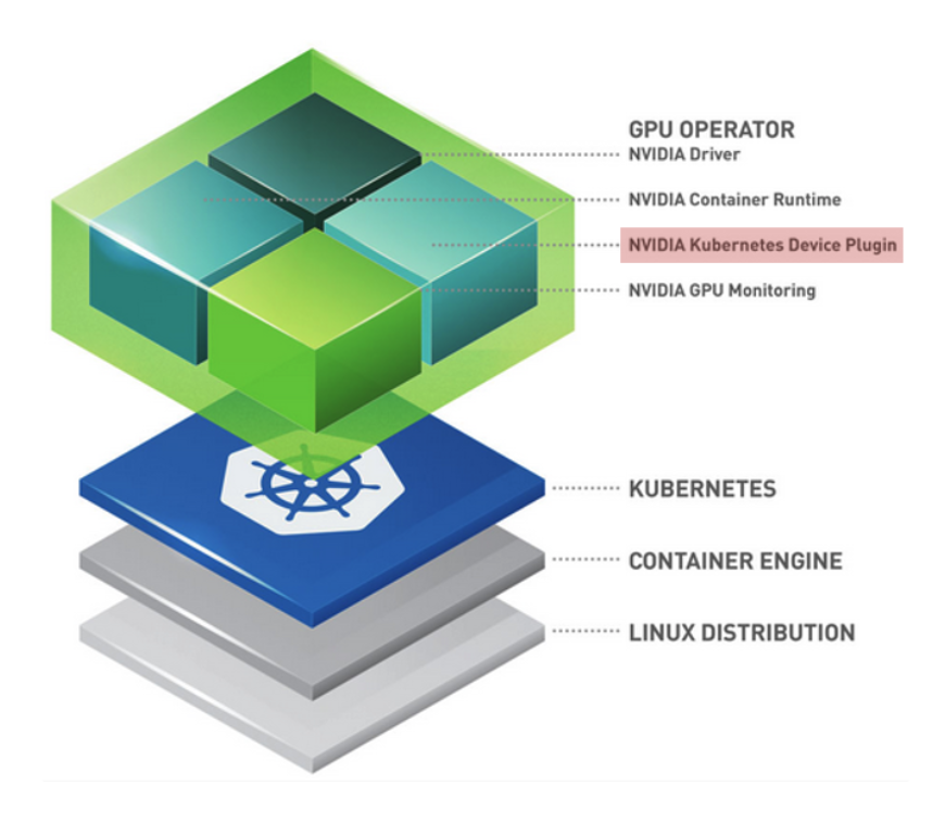
As shown in the NVIDIA Cloud-Native Toolkit Stack Layer, NVIDIA presents a layered architecture for GPU utilization:
Linux Distribution: Host OS level
Container Engine (Docker/containerd): Container runtime environment
Kubernetes: Pod scheduling and management
GPU Operator (Top Layer): An operational tool that automates all these processes, with one of its core components being the NVIDIA Device Plugin.
The NVIDIA GPU Operator supports all basic Device Plugin functions — Expose Resources, Health Check, Device Allocation & Isolation — while also providing the following extensibility:
| Feature | Description |
|---|---|
| MIG (Multi-Instance GPU) Support | Enables splitting a single physical GPU into multiple virtual GPUs via MIG |
| Ecosystem Integration | Works closely with dcgm-exporter, integrating with Prometheus (monitoring) and Grafana (visualization) |
| Operational Automation | Delivered as a modern pattern that manages everything from driver installation to plugin deployment through the GPU Operator |
AMD Xilinx Device Plugin
Xilinx combines Node Feature Discovery (NFD) with the FPGA Operator to support seamless use of their FPGA devices in Kubernetes environments.
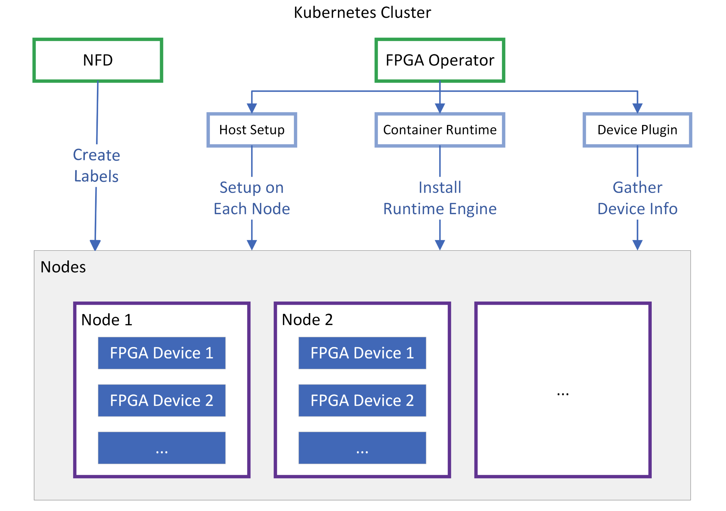
NFD scans each node to determine “What Xilinx card is installed on this node?” and creates labels for the node. Since not only the model name but also the installed Shell version, PCIe information, and others are crucial for FPGAs, it provides foundational data so the scheduler can place pods based on FPGA models or specific feature support.
Once NFD creates labels on the node, the FPGA Operator uses them to bring the node to a READY state.
| Component | Description |
|---|---|
| Host Setup | Automatically installs XRT (Xilinx Runtime) drivers and firmware on each node |
| Container Runtime | Configures a dedicated runtime engine to enable tools like xbutil and FPGA resource access within containers |
| Device Plugin | Ultimately reports virtual resources such as xilinx.com/fpga to the API Server |
HyperAccel’s first-generation LPU is based on Xilinx FPGAs. In other words, the aforementioned Xilinx Device Plugin must be applied to utilize LPUs in a Kubernetes environment.
However, directly applying the Xilinx Device Plugin as-is has functional limitations that make it difficult to use in a real server environment. What limitations exist, and how did we overcome them? Let’s now explain how we implemented the Device Plugin for LPU.
Kubernetes Device Plugin for HyperAccel LPU
HyperAccel’s first-generation LPU was designed on an FPGA (Field-Programmable Gate Array), based on the Xilinx Alveo U55C device.
Xilinx provides the Xilinx FPGA Device Plugin as open source. By deploying this plugin as a DaemonSet in the cluster, Kubernetes can recognize FPGAs as resource hardware and select them as scheduling targets. FPGAs are recognized with names like amd.com/xilinx_u55c_gen3x16_xdma_base_3-0.
Challenges with the Existing Xilinx Device Plugin
Currently, HyperAccel provides Orion servers equipped with FPGA-based LPUs, with 8 LPU devices installed in each Orion server.
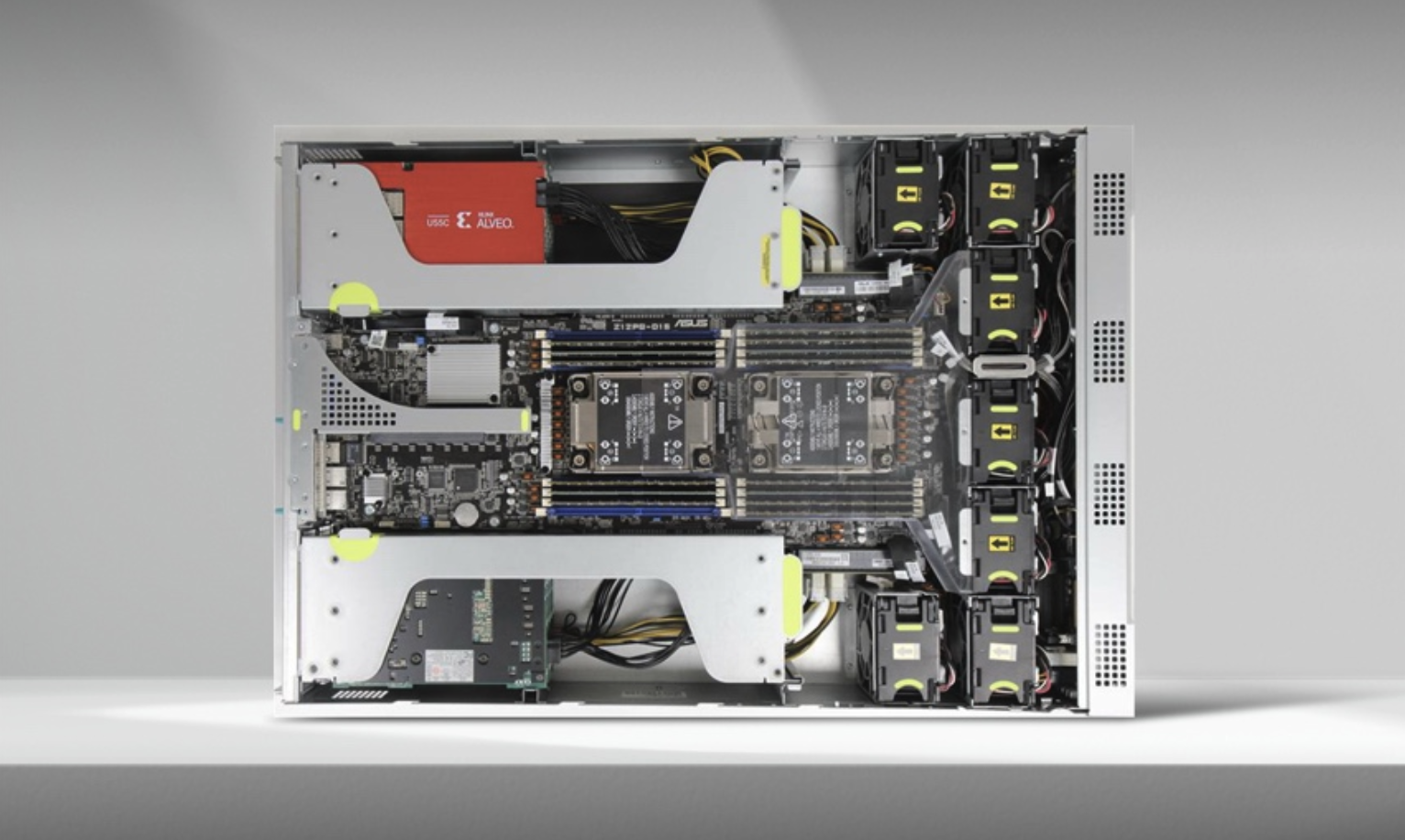
The 8 LPUs are connected in a Ring-Topology configuration.
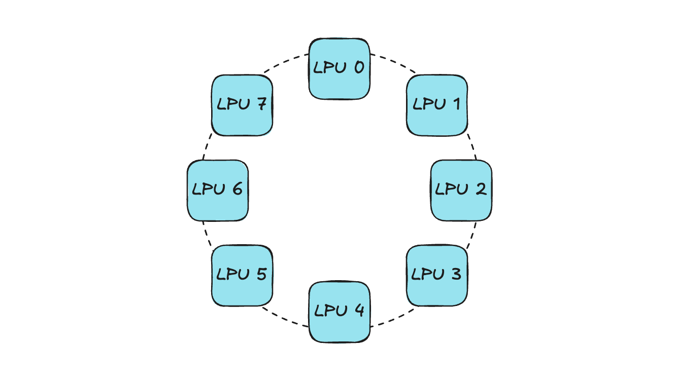
The existing Xilinx FPGA Device Plugin can only convey information like “Is the number of IDLE devices on the current node greater than the number of devices requested by the current pod?” — so the scheduler selects the node for pod placement based solely on this. If allocation is done without considering device topology, connectivity issues can arise.
Let’s look at an example. Assume a pod requests 4 LPUs within an Orion server. When a device allocation request comes in, the Device Plugin sends the list of IDLE devices to Kubelet, and Kubelet then randomly selects devices based on this list.
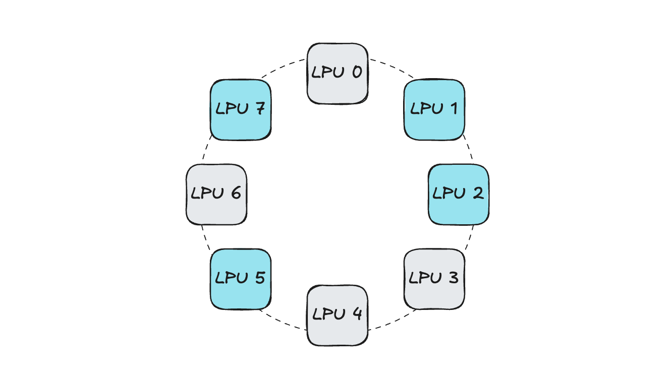
In such a situation, if devices are selected without considering connectivity:
Since the 4 LPUs are not connected to each other, operations like distributed inference become difficult. (Parallel communication and LPU-to-LPU activation synchronization are impossible)
If a future pod requesting 4 LPUs is scheduled, the same problem occurs. (The IDLE device count is satisfied for scheduling, but there is no connectivity between devices)
This not only makes distributed workloads using multiple LPUs difficult, but also causes resource fragmentation within the Orion server, reducing server-level utilization.
Due to these limitations, in internal development and testing environments with Orion servers and external PoC environments, only the approach of allocating either 1 or all LPUs could be applied. With this 1 or ALL allocation method, when multi-device development or testing is needed on Kubernetes, it becomes difficult for multiple developers to work simultaneously on a single Orion server. To overcome this problem, we developed the Orion Device Plugin in-house for more flexible device utilization in a Kubernetes-based development environment.
Orion Device Plugin
The Orion Device Plugin is a component that adds Topology-Aware allocation functionality on top of the existing Xilinx Device Plugin.
Using the in-house developed HyperDex-Toolchain, a network table showing the connectivity of LPUs within the Orion server can be extracted. Based on the number of LPUs requested by the Pod and the connectivity status of IDLE LPUs extracted from the network table, the optimal device allocation combination is determined. The Device Plugin conveys this list to Kubelet through the GetPreferredAllocation function described earlier, and Kubelet allocates LPUs to the Pod accordingly.
Using the developed component, the Orion server is currently being used in various ways:
In the Kubernetes-based in-house development environment, fully isolated LPUs within the Orion server are provided to FPGA developers. In other words, multiple developers can work simultaneously on a single Orion server without device interference.
During HyperAccel Chat Demos running on the Orion server, multiple models can be served simultaneously on the same Orion server.
When conducting customer PoCs, if there is a need to test on a Kubernetes environment, the Device Plugin is provided alongside.
Bertha Device Plugin
HyperAccel’s next-generation ASIC chip, Bertha, is about to be released!
Since Bertha is an entirely new proprietary ASIC chip from HyperAccel, utilizing it in a Kubernetes environment requires developing a Bertha Operator that includes components such as the Device Plugin, NFD, and Metric Exporter. We are currently developing the Cloud-Native Software Stack for Bertha together with Namyoon Kim (Author, LinkedIn) from the ML team.
DRA in Kubernetes
So far, we have introduced the Device Plugin — an essential component for utilizing new devices in Kubernetes — and explored how HyperAccel leverages it in our development environment. However, Device Plugins also have some limitations.
Limitations of the Kubernetes Device Plugin
Hardware management through Device Plugins has the following limitations:
Static allocation: Resource allocation is based simply on the number of devices requested.
Lack of complex configuration: It is difficult to dynamically reflect detailed hardware settings (e.g., GPU partitioning, memory bandwidth configuration) at Pod request time.
Difficulty with resource sharing: Implementing scenarios where multiple pods flexibly share a single resource is complex.
DRA (Dynamic Resource Allocation)
Kubernetes DRA is a newly introduced framework actively being adopted to overcome the limitations of existing Device Plugins and manage custom hardware resources like GPUs and FPGAs with much greater flexibility and granularity.
DRA is designed to request and allocate hardware resources in a manner similar to using storage (PVC/PV). Simply put, whereas before you could only say “Give me 1 LPU,” with DRA you can make much more complex requests like “Please dynamically allocate an LPU with settings optimized for a specific model’s inference.”
Core Components of DRA
DRA clearly separates how resources are defined and requested into Allocation and Usage.
| Component | Description |
|---|---|
| ResourceClaim | An object where users define and request needed resources (e.g., “1 GPU with 16GB or more”) — similar to PVC |
| ResourceClass | Defines the type of resource and the driver to handle it — similar to StorageClass |
| ResourceSlice | A data unit containing detailed information (model, capacity, status, etc.) about devices actually present on each node |
| DRA Driver | A plugin provided by specific hardware vendors, responsible for actual hardware preparation and allocation |
Device Plugin vs DRA
| Feature | Device Plugin | DRA |
|---|---|---|
| Resource Model | Integer-based (e.g., hyperaccel.ai/lpu: 1) | Object-based (ResourceClaim) |
| Parameter Passing | Very limited (using Annotations, etc.) | Highly flexible (Custom parameter support) |
| Scheduling | Simple count check | Can reflect complex constraints |
| Lifecycle | Fixed at Pod execution time | Can be allocated/released independently of the Pod |
With the release of Kubernetes v1.34 in the second half of 2025, major DRA features have transitioned to General Availability (GA). As a result, DRA is being standardized for managing accelerators like NVIDIA GPUs in the latest cloud environments (GKE, EKS, etc.) and on-premises AI clusters.
HyperAccel is also keeping pace and preparing to support the use of Bertha with DRA in Kubernetes environments!
In Summary…
In this article — the third installment of the Building an In-House Dev Environment on Kubernetes series — we introduced what the Kubernetes Device Plugin is, the development process of the Device Plugin for utilizing HyperAccel’s LPU in Kubernetes, and DRA, a technology for more flexible resource allocation.
For a market-competitive LPU, it is important to design well at the HW level, but an optimized SW stack must also accompany it. Supporting the smooth use of LPU on top of the most widely used Kubernetes environment is a critical challenge for chip success!
Our ML team’s DevOps division is developing Cloud-Native Toolkit software for HyperAccel LPU’s potential customers. Components such as Device Plugins and DRAs, which form the foundation of this software, enable seamless use of the LPU within computing nodes.
Thank you for reading to the end!
P.S.: HyperAccel is Hiring!
HyperAccel has all team members working hard toward the release of an LLM acceleration ASIC chip! As a company that covers not only HW and SW but also end-to-end inference AI technology, outstanding talents across all areas are working together. We are growing rapidly together, learning not just in a single field but gaining broad and deep knowledge while working with amazing colleagues!
Our ML team’s DevOps division provides and manages development environments to boost in-house developer productivity, and develops Cloud-Native Toolkit to effectively support cloud-level utilization of LPU chips.
If you’re interested in the technologies HyperAccel works with, please apply through HyperAccel Career!